🏭 Case Studies from Operational Plastic to Fuel Plants


Case Studies from Operational Plastic to Fuel Plants

1. India – Small-Scale Modular Pyrolysis Plant (5 TPD)

Location: Gujarat, India
Operator: GreenEnvy Tech Pvt. Ltd.
Feedstock: Mixed post-consumer plastics (LDPE, HDPE, PP)

Key Features:

  • Modular skid-mounted design for rural deployment

  • Operates at 450–500°C under vacuum

  • Uses ceramic wool insulation and indirect heating via thermic oil

Performance:

  • Yield: 60–65% fuel oil, 20% gas, 10% char

  • Output used for internal diesel generator

  • Fully automated with PLC controls and gas recycling loop

Challenges:

  • Impurities in mixed waste required pre-washing unit

  • Catalyst fouling reduced yield after 4 months (solved by switching to alumino-silicate)


2. USA – Industrial Scale Plant (25 TPD)

Location: Ohio, USA
Operator: RES Polyflow (now Brightmark Energy)
Feedstock: LDPE films, mixed packaging waste, low-grade post-MRF residue

Key Features:

  • Horizontal rotary kiln pyrolysis

  • Operates in batch-mode with 8-hour cycles

  • Uses synthetic zeolite catalyst

  • Designed with integrated emission treatment (scrubber + activated carbon)

Performance:

  • Oil Yield: ~68%

  • 100% of non-condensable gases reused for heating

  • End product certified as off-road diesel (ASTM D975-compliant)

Lessons Learned:

  • Proper size reduction critical for uniform heat transfer

  • Gas cleaning system needs daily maintenance for optimal VOC removal


3. Japan – Compact Urban Plant (10 TPD)

Location: Osaka, Japan
Operator: Blest Co. Ltd.
Feedstock: Clean HDPE & PP industrial waste

Key Features:

  • Compact design for urban siting

  • Fully enclosed system with odor control

  • Fast startup time: <2 hours

Outputs:

  • Fuel: Paraffinic oil used in small engines

  • Offgas: Compressed and bottled for use as backup fuel

  • Char: Sold as filler for asphalt products

Innovations:

  • Real-time process analytics (IR sensors)

  • CO₂-neutral cycle by integrating solar-powered heating


4. Kenya – Community-Based Plant (2 TPD)

Location: Kisumu, Kenya
Operator: EcoFuel Africa
Feedstock: Agricultural plastic waste and bags

Key Features:

  • Locally fabricated fixed-bed reactor

  • Manual loading and gravity discharge

  • Operated by women cooperatives as income generation

Products:

  • Oil used for powering irrigation pumps

  • Gas flared due to lack of storage system

  • Ash used in brick making

Social Impact:

  • Created 25+ jobs

  • Reduced open burning of plastic

  • Enabled clean water access through pump deployment


5. China – Co-Processing in Cement Kilns

Location: Shandong, China
Operator: SINOMA Cement Plant
Feedstock: Shredded mixed plastics (<50 mm)

Key Features:

  • No separate pyrolysis unit: plastics co-processed in cement kiln at >900°C

  • Energy recovered directly in clinker production

  • No fuel oil produced, but fossil fuel savings achieved

Benefits:

  • Replaces up to 10% coal input

  • No additional emissions (confirmed via stack testing)

  • Integrated into waste management plan of city


📊 Comparative Summary Table

Case

Capacity

Feedstock

Yield (Oil)

Energy Use

Tech Highlights

India

5 TPD

Mixed plastics

60–65%

Thermic oil

Modular, off-grid ready

USA

25 TPD

MRF residue

~68%

Gas reuse

ASTM-grade diesel

Japan

10 TPD

Clean HDPE/PP

70%

Low

Urban setup, odor control

Kenya

2 TPD

Agri waste

55%

Biomass

Community-led design

China

20–50 TPD

Shredded mix

N/A

Kiln-integrated

Co-processing, no residue


📝 Key Takeaways

  • Feedstock quality significantly influences oil yield and process stability.

  • Catalyst selection and pre-treatment are critical to long-term performance.

  • Automation and safety systems are vital, even at small scales.

  • Plants that integrate energy recycling and environmental controls achieve the best sustainability profiles.

  • Social impact and economic viability are major drivers in developing countries.

📌 If you are interested in seeing articles in other science & engineering, you can find them 👉 here

🔧 Detailed Design Calculations: Plastic to Fuel Pyrolysis Plant (10 TPD)


Detailed Design Calculations: Plastic to Fuel Pyrolysis Plant (10 TPD)

1. Input Data and Assumptions

Parameter

Value

Unit

Plant capacity

10,000

kg/day

Operation time

20

hours/day

Bulk density of plastic flakes

0.25

kg/L

Plastic to oil yield (avg.)

70

%

Heating value of feedstock

35

MJ/kg

Specific heat of plastic

2.0

kJ/kg·K

Target pyrolysis temp.

450

°C

Ambient temp.

30

°C


2. Material Balance

Daily Feedstock:

  • 10,000 kg plastic/day

Estimated Product Yields:

  • Oil: 70% → 7,000 kg/day

  • Gas: 20% → 2,000 kg/day

  • Char: 10% → 1,000 kg/day


3. Energy Requirement for Pyrolysis

Heating Load (Q):

Q=mcΔTQ = m \cdot c \cdot \Delta T
  • m=10,000m = 10,000 kg/day

  • c=2.0c = 2.0 kJ/kg·K

  • ΔT=45030=420\Delta T = 450 - 30 = 420 °C

Q=10,0002.0420=8,400,000 kJ/dayQ = 10,000 \cdot 2.0 \cdot 420 = 8,400,000 \text{ kJ/day}

Convert to kWh:

8,400,000÷3600=2,333 kWh/day8,400,000 \div 3600 = 2,333 \text{ kWh/day}

Add heat losses (assume 25%):

Qtotal=2,3331.25=2,916 kWh/dayQ_{\text{total}} = 2,333 \cdot 1.25 = 2,916 \text{ kWh/day}

4. Reactor Sizing

Assume 4 hours residence time and 250 kg/h feeding rate

Volume=MassDensity=1,000250=4.0 m3\text{Volume} = \frac{\text{Mass}}{\text{Density}} = \frac{1,000}{250} = 4.0 \text{ m}^3

Assuming horizontal cylindrical reactor:

Volume=πD24L\text{Volume} = \pi \cdot \frac{D^2}{4} \cdot L

Assume L = 4 m:

4=πD244D=1.13 m4 = \pi \cdot \frac{D^2}{4} \cdot 4 \Rightarrow D = 1.13 \text{ m}

=> Reactor Size: 4 m length x 1.13 m diameter


5. Condenser Sizing

Condense 7,000 kg/day of vapor to liquid

  • Vapor flow rate: 350 kg/h

  • Latent heat of condensation: 300 kJ/kg

  • Cooling water ΔT: 10°C

Q=mL=350300=105,000 kJ/hQ = m \cdot L = 350 \cdot 300 = 105,000 \text{ kJ/h}

Cooling water flow rate:

Q=mcΔTm=105,0004.1810=2,510 kg/h2.5 m3/hQ = m \cdot c \cdot \Delta T \Rightarrow m = \frac{105,000}{4.18 \cdot 10} = 2,510 \text{ kg/h} \approx 2.5 \text{ m}^3/h

6. Gas Scrubber and Flare Sizing

Combustible Gas: 2,000 kg/day (~100 kg/h)

Assume methane equivalent:

Energy value=50MJ/kg5,000MJ/day=1,389kWh/day\text{Energy value} = 50 MJ/kg \Rightarrow 5,000 MJ/day = 1,389 kWh/day

Flare size estimation:

Assume 10 kg/h continuous flaring

Use flame diameter ≈ 0.3–0.5 m with vertical pipe height ≈ 3 m


7. Fuel Oil Storage

Yield = 7,000 kg/day, assume density = 0.85 kg/L

Volume=70000.85=8,235 L/day\text{Volume} = \frac{7000}{0.85} = 8,235 \text{ L/day}

For 3 days buffer:
Storage Tank = 25,000 L (use 30,000 L for contingency)


8. Char and Ash Handling

Char output = 1,000 kg/day
Assume stored in 1-ton jumbo bags or silos

Silo size (1.2 bulk density):

Volume=1,0001.2=0.83 m3/day\text{Volume} = \frac{1,000}{1.2} = 0.83 \text{ m}^3/day

Use 3–5 m³ silo for buffer capacity.


9. Electrical Power Consumption (Estimation)

Equipment

Power (kW)

Duration (hr)

Energy (kWh)

Reactor Heater

100

20

2,000

Condenser Pumps

5

20

100

Feed System

2

20

40

Scrubber/Fan

3

20

60

Automation + Lighting

5

24

120

Total Daily

2,320 kWh


✅ Summary Table

Item

Design Value

Reactor Volume

4 m³

Reactor Dimensions

Ø1.13 m × 4 m

Energy Required

2,916 kWh/day

Condenser Water Flow

2.5 m³/h

Daily Oil Output

7,000 kg

Storage Tank Size

30 m³

Total Electric Consumption

~2,320 kWh/day


📌 If you are interested in seeing articles in other science & engineering, you can find them 👉 here

Plastic to Fuel: Pyrolysis Technology – From Scientific Principles to Real-World Application


The growing menace of plastic waste pollution has driven a wave of innovation in sustainable recycling technologies. Among the most promising methods is Plastic Pyrolysis—a thermochemical process that transforms plastic waste into fuel.

The growing menace of plastic waste pollution has driven a wave of innovation in sustainable recycling technologies. Among the most promising methods is Plastic Pyrolysis—a thermochemical process that transforms plastic waste into fuel. This article discusses the fundamental science, engineering design, system components, safety measures, input-output balance, and environmental implications of plastic-to-fuel technology using pyrolysis.


1. Basic Scientific Principles of Pyrolysis

Pyrolysis is governed by principles of thermodynamics and chemical kinetics. It is the thermal decomposition of organic material in the absence of oxygen, preventing combustion and promoting molecular breakdown.

Key principles involved include:

  • First Law of Thermodynamics: Energy conservation during heat input and chemical transformation.

  • Second Law of Thermodynamics: Entropy increases as complex polymers are broken into smaller molecules.

  • Chemical Kinetics: Reaction rates depend on temperature, catalyst, and molecular structure.

  • Le Chatelier’s Principle: Used in catalytic pyrolysis to steer reactions toward desirable outputs (e.g., fuel oil).

Common plastic types such as polyethylene (PE), polypropylene (PP), and polystyrene (PS) are thermally cracked into smaller hydrocarbon chains that can be condensed into oil.


2. Process Flow and Technology Implementation

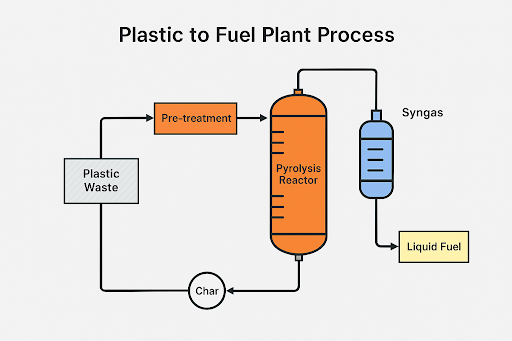
The plastic-to-fuel process consists of the following stages:

  1. Feedstock Sorting and Pre-treatment

  2. Shredding to Uniform Particle Size

  3. Feeding into the Pyrolysis Reactor

  4. Thermal Decomposition (200–900°C) in Oxygen-Free Environment

  5. Condensation of Hydrocarbon Vapors into Oil

  6. Separation of Byproducts (Gas and Char)

  7. Oil Refining for End-Use


📌 PFD – Plastic to Fuel Process Flow Diagram

Process Flow Diagram (PFD) of the Plastic to Fuel Pyrolysis Plant


3. Key Components and Auxiliary Systems

  • Feed Hopper: Receives pretreated plastic waste.

  • Pyrolysis Reactor: Sealed chamber (SS316 or Inconel) that provides uniform heating.

  • Heating System: Electrical or gas-fired units for controlled temperature rise.

  • Catalyst Unit: Zeolite or silica-alumina to enhance cracking efficiency.

  • Condensers and Fractionation Units: Stainless steel heat exchangers for condensing vapors.

  • Gas Scrubbers and Flare Stack: For safe exhaust gas handling.

  • Char Collection System: For solid residue disposal or reuse.

  • PLC/SCADA Control Panel: For automation and safety interlock systems.


📌 Layout – Plastic to Fuel Plant Process Layout Diagram


Technical Layout of Plastic to Fuel Conversion Plant

4. Construction Materials and Standards

  • Reactor and Condenser: SS304, SS316, Inconel, or Hastelloy for high-temperature resistance.

  • Piping and Seals: PTFE or Viton-based materials.

  • Refractory Lining: Ceramic fiber or alumina bricks.

  • Safety Standards:

    • ASME Section VIII – Pressure vessel standards

    • API 650 – Tank fabrication standards

    • ISO 14001 – Environmental compliance

    • OSHA 1910 – Worker safety


5. Input Materials and Output Products

Acceptable Plastic Waste Feedstocks:

  • Polyethylene (PE)

  • Polypropylene (PP)

  • Polystyrene (PS)

Outputs:

  • Liquid Oil (TPO): Used as fuel for generators, engines, or refined into diesel.

  • Syngas: Recycled as heating fuel within the plant.

  • Char: Used in construction or pigment manufacturing.

Byproducts Applications:

  • Light oil: Fuel additive.

  • Heavy oil: Industrial heating.

  • Carbon black: Reinforcement filler.

  • Gas: Used for energy recovery within the process loop.


📌 Graph – Plastic to Fuel Output Comparison

Estimated Fuel Yield Based on Different Plastic Types


6. Environmental Impact and Mitigation

Risks:

  • VOC emissions

  • Chlorine release (if PVC is processed)

  • Explosion risk from syngas

  • Water or soil contamination

Mitigation Measures:

  • Oxygen sensors to ensure oxygen-free operation.

  • Scrubbers to capture dioxins and HCl.

  • Flare system for excess gas burning.

  • Regular PPE usage and personnel training.

  • Emergency shutdown systems (ESD).

Environmental Benefits:

  • Reduces landfill plastic burden.

  • Prevents ocean plastic accumulation.

  • Provides circular economy fuel.

  • Lowers dependence on fossil fuel refining.


7. International Standards and Compliance

The system should comply with:

  • EPA guidelines – Emission and fuel quality

  • ISO 45001 – Occupational safety

  • REACH / RoHS – Chemical content standards

  • Basel Convention – Waste material handling and export


8. Conclusion

Plastic pyrolysis presents a scalable and circular solution to the global plastic waste crisis. The conversion of non-recyclable plastics into usable fuel not only reduces environmental impact but also offers significant energy recovery. With proper engineering design, process control, and environmental safeguards, this technology can be safely integrated into modern waste management and renewable energy infrastructures.

📌 If you are interested in seeing articles in other science & engineering, you can find them 👉 here


From Engineer to Thought Leader: Building Your Voice in the Digital Space

In today’s digital world, being an excellent engineer is no longer enough. To truly stand out, you must build your personal brand and share ...