1. Input Data and Assumptions
|
Parameter |
Value |
Unit |
|
Plant capacity |
10,000 |
kg/day |
|
Operation time |
20 |
hours/day |
|
Bulk density of plastic flakes |
0.25 |
kg/L |
|
Plastic to oil yield (avg.) |
70 |
% |
|
Heating value of feedstock |
35 |
MJ/kg |
|
Specific heat of plastic |
2.0 |
kJ/kg·K |
|
Target pyrolysis temp. |
450 |
°C |
|
Ambient temp. |
30 |
°C |
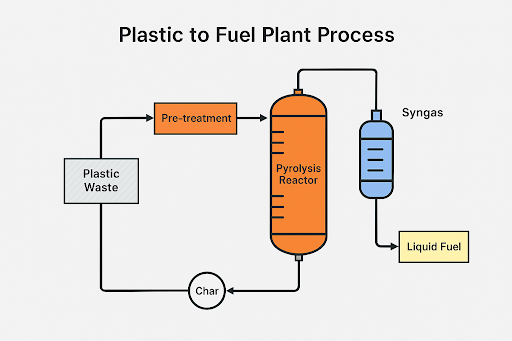
2. Material Balance
Daily Feedstock:
-
10,000 kg plastic/day
Estimated Product Yields:
-
Oil: 70% → 7,000 kg/day
-
Gas: 20% → 2,000 kg/day
-
Char: 10% → 1,000 kg/day
3. Energy Requirement for Pyrolysis
Heating Load (Q):
-
kg/day
-
kJ/kg·K
-
°C
Convert to kWh:
Add heat losses (assume 25%):
4. Reactor Sizing
Assume 4 hours residence time and 250 kg/h feeding rate
Assuming horizontal cylindrical reactor:
Assume L = 4 m:
=> Reactor Size: 4 m length x 1.13 m diameter
5. Condenser Sizing
Condense 7,000 kg/day of vapor to liquid
-
Vapor flow rate: 350 kg/h
-
Latent heat of condensation: 300 kJ/kg
-
Cooling water ΔT: 10°C
Cooling water flow rate:
6. Gas Scrubber and Flare Sizing
Combustible Gas: 2,000 kg/day (~100 kg/h)
Assume methane equivalent:
Flare size estimation:
Assume 10 kg/h continuous flaring
Use flame diameter ≈ 0.3–0.5 m with vertical pipe height ≈ 3 m
7. Fuel Oil Storage
Yield = 7,000 kg/day, assume density = 0.85 kg/L
For 3 days buffer:
Storage Tank = 25,000 L (use 30,000 L for contingency)
8. Char and Ash Handling
Char output = 1,000 kg/day
Assume stored in 1-ton jumbo bags or silos
Silo size (1.2 bulk density):
Use 3–5 m³ silo for buffer capacity.
9. Electrical Power Consumption (Estimation)
|
Equipment |
Power
(kW) |
Duration
(hr) |
Energy
(kWh) |
|
Reactor Heater |
100 |
20 |
2,000 |
|
Condenser Pumps |
5 |
20 |
100 |
|
Feed System |
2 |
20 |
40 |
|
Scrubber/Fan |
3 |
20 |
60 |
|
Automation + Lighting |
5 |
24 |
120 |
|
Total Daily |
2,320
kWh |
✅ Summary Table
|
Item |
Design
Value |
|
Reactor Volume |
4
m³ |
|
Reactor Dimensions |
Ø1.13
m × 4 m |
|
Energy Required |
2,916
kWh/day |
|
Condenser Water Flow |
2.5
m³/h |
|
Daily Oil Output |
7,000
kg |
|
Storage Tank Size |
30
m³ |
|
Total Electric Consumption |
~2,320
kWh/day |