Plastic to Fuel: Pyrolysis Technology – From Scientific Principles to Real-World Application


The growing menace of plastic waste pollution has driven a wave of innovation in sustainable recycling technologies. Among the most promising methods is Plastic Pyrolysis—a thermochemical process that transforms plastic waste into fuel.

The growing menace of plastic waste pollution has driven a wave of innovation in sustainable recycling technologies. Among the most promising methods is Plastic Pyrolysis—a thermochemical process that transforms plastic waste into fuel. This article discusses the fundamental science, engineering design, system components, safety measures, input-output balance, and environmental implications of plastic-to-fuel technology using pyrolysis.


1. Basic Scientific Principles of Pyrolysis

Pyrolysis is governed by principles of thermodynamics and chemical kinetics. It is the thermal decomposition of organic material in the absence of oxygen, preventing combustion and promoting molecular breakdown.

Key principles involved include:

  • First Law of Thermodynamics: Energy conservation during heat input and chemical transformation.

  • Second Law of Thermodynamics: Entropy increases as complex polymers are broken into smaller molecules.

  • Chemical Kinetics: Reaction rates depend on temperature, catalyst, and molecular structure.

  • Le Chatelier’s Principle: Used in catalytic pyrolysis to steer reactions toward desirable outputs (e.g., fuel oil).

Common plastic types such as polyethylene (PE), polypropylene (PP), and polystyrene (PS) are thermally cracked into smaller hydrocarbon chains that can be condensed into oil.


2. Process Flow and Technology Implementation

The plastic-to-fuel process consists of the following stages:

  1. Feedstock Sorting and Pre-treatment

  2. Shredding to Uniform Particle Size

  3. Feeding into the Pyrolysis Reactor

  4. Thermal Decomposition (200–900°C) in Oxygen-Free Environment

  5. Condensation of Hydrocarbon Vapors into Oil

  6. Separation of Byproducts (Gas and Char)

  7. Oil Refining for End-Use
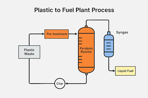

๐Ÿ“Œ PFD – Plastic to Fuel Process Flow Diagram

Process Flow Diagram (PFD) of the Plastic to Fuel Pyrolysis Plant


3. Key Components and Auxiliary Systems

  • Feed Hopper: Receives pretreated plastic waste.

  • Pyrolysis Reactor: Sealed chamber (SS316 or Inconel) that provides uniform heating.

  • Heating System: Electrical or gas-fired units for controlled temperature rise.

  • Catalyst Unit: Zeolite or silica-alumina to enhance cracking efficiency.

  • Condensers and Fractionation Units: Stainless steel heat exchangers for condensing vapors.

  • Gas Scrubbers and Flare Stack: For safe exhaust gas handling.

  • Char Collection System: For solid residue disposal or reuse.

  • PLC/SCADA Control Panel: For automation and safety interlock systems.


๐Ÿ“Œ Layout – Plastic to Fuel Plant Process Layout Diagram


Technical Layout of Plastic to Fuel Conversion Plant

4. Construction Materials and Standards

  • Reactor and Condenser: SS304, SS316, Inconel, or Hastelloy for high-temperature resistance.

  • Piping and Seals: PTFE or Viton-based materials.

  • Refractory Lining: Ceramic fiber or alumina bricks.

  • Safety Standards:

    • ASME Section VIII – Pressure vessel standards

    • API 650 – Tank fabrication standards

    • ISO 14001 – Environmental compliance

    • OSHA 1910 – Worker safety


5. Input Materials and Output Products

Acceptable Plastic Waste Feedstocks:

  • Polyethylene (PE)

  • Polypropylene (PP)

  • Polystyrene (PS)

Outputs:

  • Liquid Oil (TPO): Used as fuel for generators, engines, or refined into diesel.

  • Syngas: Recycled as heating fuel within the plant.

  • Char: Used in construction or pigment manufacturing.

Byproducts Applications:

  • Light oil: Fuel additive.

  • Heavy oil: Industrial heating.

  • Carbon black: Reinforcement filler.

  • Gas: Used for energy recovery within the process loop.


๐Ÿ“Œ Graph – Plastic to Fuel Output Comparison

Estimated Fuel Yield Based on Different Plastic Types


6. Environmental Impact and Mitigation

Risks:

  • VOC emissions

  • Chlorine release (if PVC is processed)

  • Explosion risk from syngas

  • Water or soil contamination

Mitigation Measures:

  • Oxygen sensors to ensure oxygen-free operation.

  • Scrubbers to capture dioxins and HCl.

  • Flare system for excess gas burning.

  • Regular PPE usage and personnel training.

  • Emergency shutdown systems (ESD).

Environmental Benefits:

  • Reduces landfill plastic burden.

  • Prevents ocean plastic accumulation.

  • Provides circular economy fuel.

  • Lowers dependence on fossil fuel refining.


7. International Standards and Compliance

The system should comply with:

  • EPA guidelines – Emission and fuel quality

  • ISO 45001 – Occupational safety

  • REACH / RoHS – Chemical content standards

  • Basel Convention – Waste material handling and export


8. Conclusion

Plastic pyrolysis presents a scalable and circular solution to the global plastic waste crisis. The conversion of non-recyclable plastics into usable fuel not only reduces environmental impact but also offers significant energy recovery. With proper engineering design, process control, and environmental safeguards, this technology can be safely integrated into modern waste management and renewable energy infrastructures.

๐Ÿ“Œ If you are interested in seeing articles in other science & engineering, you can find them ๐Ÿ‘‰ here


⚙️ Anaerobic Biogas Plant

 A well-engineered anaerobic biogas plant is designed to deliver a positive net energy yield by ensuring that the energy outputs significantly exceed the energy inputs.

⚙️ Energy Balance and Automation System A Smart Approach to Efficiency, Monitoring, and Control


๐Ÿ”‹ 1. Energy Balance of Anaerobic Biogas Plant

A well-engineered anaerobic biogas plant is designed to deliver a positive net energy yield by ensuring that the energy outputs significantly exceed the energy inputs. The energy balance is calculated by comparing the operational energy requirements (thermal, mechanical, and electrical) with the energy produced in the form of biogas.

๐Ÿ”ข Typical Energy Input (kWh/ton feedstock):

  • Heating (Thermophilic range, 50–55°C): 30–60 kWh

  • Agitation and Mixing: 10–15 kWh

  • Pumps and Feedstock Transfer: 5–10 kWh

  • Gas Compression (for CBG): 20–50 kWh

  • Biogas Purification: 15–30 kWh

⚡ Energy Output (kWh/ton feedstock):

  • Biogas Production: 180–250 Nm³/ton

  • Methane Content (CH₄): ~55–65%

  • Usable Energy (Electrical + Thermal): 500–650 kWh/ton

๐Ÿ“˜ Net Energy Gain: ~400–500 kWh/ton feedstock, depending on substrate quality, system insulation, and digester efficiency.

๐Ÿ”„ Energy Recovery Techniques:

  • Combined Heat and Power (CHP) Units: Convert biogas into electricity while recovering heat for digester heating.

  • Heat Integration Systems: Recover heat from CHP flue gases and engine jackets.

  • Feedstock Pre-heaters: Utilize solar thermal or exhaust heat to pre-condition the input substrate, reducing load on primary heating systems.


๐Ÿ–ฅ️ 2. Automation System: SCADA and PLC Integration

Automation is an integral component for modern anaerobic digestion systems, enabling precise process control, enhanced safety, real-time monitoring, and optimized biogas yields.

๐Ÿง  Key Features of the Automation System:

  • PLC (Programmable Logic Controller)

    • Local control of field devices

    • Logic-based control of pumps, agitators, heating systems, gas valves

    • Alarms and interlocks

  • SCADA (Supervisory Control and Data Acquisition)

    • Graphical user interface (GUI) with real-time data

    • Control of process parameters from central or remote terminals

    • Event and trend logging with historical data storage

    • Secure remote access for monitoring and troubleshooting

๐Ÿ“ถ Communication Protocols:

  • Modbus TCP/IP, Profibus for device-level communication

  • Ethernet/IP for enterprise and cloud integration

  • GSM or VPN modules for remote access

๐Ÿ“ Typical Control Points Monitored via SCADA:

  • pH levels in digester (optimal range: 6.8–7.5)

  • Temperature in primary digester (mesophilic or thermophilic)

  • Biogas flowrate and composition (CH₄, H₂S, CO₂)

  • Substrate input quantity and mixing ratios

  • Agitator status and retention time tracking

  • Digestate level and backpressure data

  • H₂S scrubber and filter differential pressure

๐Ÿ’ป Automation Benefits:

  • Minimizes manual intervention and operator errors

  • Increases process stability and overall biogas yield

  • Real-time alerts reduce downtime and improve safety

  • Historical data supports predictive maintenance

  • Enables performance reporting for ESG and carbon credit validation


๐Ÿ“ Recommended Automation and Instrumentation Standards:

  • ISA-88 / ISA-95: For batch process automation and integration

  • IEC 61131-3: Programming standards for PLCs

  • IEC 61511: Functional safety for industrial process systems

  • OPC UA: For seamless interoperability across automation systems

Conclusion: A well-automated anaerobic biogas plant, designed with robust energy integration, offers superior operational efficiency, reduced OPEX, higher uptime, and compliance with modern energy and safety regulations. This smart design approach not only enhances ROI but also positions the plant for eligibility in green energy incentives and carbon market programs.

๐Ÿ”ง Sample of Technical Engineering Document: Anaerobic Biogas Plant – Capacity 10 Tons/Day


๐Ÿ“ˆ 1. Process Flow Diagram (PFD) – Conceptual Description

A 10-ton/day anaerobic biogas plant typically processes organic feedstock (e.g., livestock manure, food/agro waste) via the following stages:

Feedstock Pre-treatment Anaerobic Digestion Biogas Collection Gas Upgrading Biogas Storage Utilization (CBG/CHP) Digestate Processing Treated Water Reuse

Main Process Units:

  1. Feedstock Reception Hopper & Pre-mixing Tank
  2. Primary Digester Tank (CSTR, mesophilic @ 35–40°C)
  3. Gas Dome & Pressure Equalization System
  4. H₂S Scrubber ➝ Moisture Trap ➝ Activated Carbon Filter
  5. PSA Unit for CO₂ Separation ➝ CBG Compressor
  6. Cascade Gas Cylinder Storage
  7. CHP Unit or Gas Bottling Station
  8. Solid-Liquid Separator for Digestate
  9. Sludge Dryer ➝ Pelletizer ➝ Organic Fertilizer Storage
  10. WWTP (SBR type) for effluent

๐Ÿ› ️ 2. Piping & Instrumentation Diagram (P&ID) – Main Loops Description

A simplified representation of key control loops and piping structure:

  • FT-101: Feedstock Flow Meter
  • P-102: Feed Pump to Digester
  • TIC-103: Digester Temperature Control via Jacket Heating System
  • LIT-104: Digester Liquid Level Transmitter
  • PIT-105: Gas Dome Pressure Indicator
  • GCV-106: Gas Control Valve to Scrubber
  • AIC-107: H₂S Analyzer Controller
  • P-108: Booster Blower to PSA System
  • FIC-109: Flow Controller to Storage Cylinders
  • LIT-110: Sludge Tank Level Transmitter
  • MCC Panel: Connected to SCADA with all sensor inputs

Instrumentation legend available upon request.


๐Ÿ“‹ 3. Instrumentation I/O List – Main Field Devices

Tag No.

Device Description

Type

Signal

Location

FT-101

Feedstock Flow Transmitter

AI

4–20 mA

Feed Hopper Line

TIC-103

Temperature Indicator/Controller

AI/AO

4–20 mA

Digester Heating

LIT-104

Level Indicator Transmitter

AI

4–20 mA

Digester Tank

PIT-105

Pressure Indicator Transmitter

AI

4–20 mA

Gas Dome

AIC-107

Gas Composition Analyzer (H₂S, CH₄, CO₂)

AI

RS-485

Gas Line

FIC-109

Flow Indicator Controller

AI/AO

4–20 mA

PSA Outlet

ESD-111

Emergency Shutdown Switch

DI

Dry

MCC Room

V-112

Motorized Valve

DO

Relay

Gas Header

AL-113

Gas Leak Detector

AI/DI

4–20 mA

CBG Zone


๐Ÿง  4. Control Philosophy

The automation strategy is built upon a dual-tier structure: field-level PLC control and supervisory SCADA system.

A. PLC Logic & Control Loops:

  • Controls all pumps, agitators, temperature regulation via analog/digital I/O
  • Logic-based interlocks:
    • High-High Pressure → PRV Open + Shutdown Biogas Line
    • High Temp → Cut Heater + Activate Alarm
    • Gas Leak Detected → Shutdown Blower + Close Main Valve

B. SCADA Functions:

  • Graphical Interface: Real-time display of all process variables
  • Trending: Biogas output, pH, H₂S concentration, energy consumption
  • Alarms & Events: Set for all high/low limits and trip conditions
  • Reports: Daily gas yield, energy balance, feedstock stats
  • Remote Access: Optional via VPN module

C. Communication Network:

  • All devices use Modbus RTU/TCP, Ethernet/IP, integrated through industrial switch to SCADA server
  • Local HMI panel also installed near MCC for onsite operations

๐Ÿ“Š 5. Energy Balance – Based on 10 Tons/day

Assumptions:

  • Feedstock: Cattle manure + food waste
  • Organic Loading Rate: ~2.5 kg VS/m³/day
  • Biogas Yield: ~200 Nm³/ton
  • Methane Content: 60%

Category

Value

Total Biogas/day

2,000 Nm³

Usable Energy

~1,200 kWh/day

Electricity Used

~150 kWh/day

Heat Used

~200 kWh/day

Net Energy Gain

~850 kWh/day


๐Ÿ“Œ If you are interested in seeing articles that are relevant to this field, you can find them ๐Ÿ‘‰ here or here


๐Ÿ”ง Engineering & System Design of Anaerobic Biogas Plant


Anaerobic Biogas Plant A Detailed Technical Overview with Components, Standards, Materials, and Safety

A Detailed Technical Overview with Components, Standards, Materials, and Safety


1. ๐Ÿงช Anaerobic Digester System

๐Ÿ”ฉ Main Components:

  • Feedstock Storage and Preparation Tanks: Used for collecting and homogenizing organic waste.

  • Primary Digester Tank (CSTR or UASB): Sealed reactor tank (typically cylindrical) where anaerobic fermentation occurs.

  • Heating Coils & Insulation Jackets: Maintain thermophilic or mesophilic temperature range (35–55°C).

  • Gas Dome or Membrane Cover: Captures produced biogas under pressure.

  • Mixing Equipment (Agitators or Recirculation Pumps): Ensures even microbial activity and prevents sedimentation.

๐Ÿงฑ Material of Construction:

  • Reactor Walls: Reinforced Concrete (ASTM C94 / BS EN 206), lined with Epoxy or HDPE.

  • Gas Storage: Double-membrane biogas holders (PVC-coated polyester with UV resistance).

  • Piping: Stainless Steel 316L or HDPE for corrosion resistance.

๐Ÿ—️ Fabrication & Installation:

  • Civil works include deep foundation and waterproofing.

  • Precast or cast-in-situ digester tank construction.

  • Membrane dome prefabricated offsite, installed with tensioned anchoring rings.

๐Ÿ”’ Safety Equipment:

  • Pressure Relief Valves (PRV)

  • Flame Arrestors

  • Emergency Flaring Unit

  • Continuous Gas Monitoring (CH₄, H₂S, CO₂)

๐Ÿ“ Design Standards:

  • ASME BPVC (Boiler & Pressure Vessel Code)

  • ISO 23553 (Biogas safety)

  • DIN 51624 (Biomethane Quality for Vehicles)


2. ๐Ÿงผ Biogas Purification System

๐Ÿ”ฉ Main Components:

  • Scrubbers (Water or Amine): Remove H₂S and moisture.

  • Activated Carbon Filters: Capture siloxanes and VOCs.

  • Membrane Separation or PSA (Pressure Swing Adsorption): Removes CO₂ for upgrading biogas to biomethane.

๐Ÿงฑ Material of Construction:

  • Columns: SS316L or FRP (Fiberglass Reinforced Plastic)

  • Piping & valves: PTFE-lined or stainless steel

  • Moisture traps and condensate drains are standard.

๐Ÿ—️ Fabrication Process:

  • Column vessels are fabricated per ASME standards.

  • Skid-mounted PSA/membrane units are pre-assembled at factory.

๐Ÿ”’ Safety Features:

  • H₂S detectors with alarm system

  • Explosion-proof enclosures for electricals

  • Anti-static grounding for gas flow systems

๐Ÿ“ Relevant Standards:

  • ISO 15403-1 (Fuel quality for CNG)

  • ATEX Directive for explosive environments

  • NFPA 820 for combustible gas handling


3. ๐Ÿ›ข️ Compressed Biogas (CBG) System

๐Ÿ”ฉ Main Components:

  • Dryer & Cooling Unit: Removes final moisture traces.

  • Compressors (Rotary or Screw type): Raises pressure up to 250 bar.

  • Cascade Storage Cylinders: High-pressure gas storage for bottling or transport.

  • Filling Station with Nozzle Interface: For cylinder or vehicle refueling.

๐Ÿงฑ Materials:

  • Cylinder material: Carbon steel or composite (ISO 11439 compliant)

  • Compressor housing: Cast iron with anti-explosion design

๐Ÿ—️ Fabrication:

  • High-pressure components certified to PED (Pressure Equipment Directive)

  • Hydrostatic testing for cylinders and pipelines

๐Ÿ”’ Safety Systems:

  • Pressure gauges, rupture discs, and back-pressure regulators

  • Fire suppression and gas leak detection system

  • Emergency shut-off valves (ESV)

๐Ÿ“ Standards:

  • ISO 9809, ISO 11120 for gas cylinders

  • OISD (Oil Industry Safety Directorate – India)

  • ISO 16923: CNG refueling stations


4. ๐Ÿ”Œ Energy Distribution System

๐Ÿ”ฉ Key Components:

  • Pipeline Grid: For biogas delivery to nearby users.

  • Cylinder Distribution System: For remote or rural areas.

  • Smart Metering Units: Measures household or industrial consumption.

๐Ÿงฑ Material & Protection:

  • Pipelines: MDPE (Medium-Density Polyethylene), ASTM D2513

  • Joints: Electro-fusion type for leak-proof sealing

  • UV-shielded external piping for above-ground exposure

๐Ÿ—️ Fabrication:

  • Trenching and directional boring for pipeline installation

  • Prefabricated valve stations and flow control boxes

๐Ÿ”’ Safety:

  • Odorant injection to detect leaks

  • Over-pressure protection valves

  • GIS-based leak monitoring (SCADA integration)

๐Ÿ“ Codes & Standards:

  • IGEM/TD/3 for PE gas pipelines

  • ASME B31.8 – Gas Transmission and Distribution


5. ๐ŸŒŠ Wastewater Treatment Plant (WWTP)

๐Ÿ”ฉ Key Components:

  • Settling Tanks & Clarifiers: Separate solids from liquid digestate

  • Aerobic Treatment Units (SBR/MBBR): Reduces COD/BOD

  • Sludge Drying Beds or Centrifuge Units: Handles final sludge

๐Ÿงฑ Material & Equipment:

  • Clarifiers: RCC with epoxy lining

  • Aeration: Blowers (SS) with diffusers (EPDM or PTFE)

  • Screens & filters in SS304

๐Ÿ—️ Fabrication & Installation:

  • Modular units pre-installed on skids

  • PLC-based automation for dosing and aeration

๐Ÿ”’ Safety:

  • PPE for operators (chemical resistant gloves, masks)

  • Containment basins to avoid groundwater contamination

๐Ÿ“ Standards:

  • ISO 10667: Treatment of Industrial Wastewater

  • USEPA 503 for land application of biosolids

  • SNI 6989 – Indonesian wastewater quality standard


6. ♻️ Byproduct Processing Unit

๐Ÿ”ฉ Key Functional Sections:

  • Solid-Liquid Separator (Screw Press or Belt Filter): Separates digestate fractions

  • Drying & Pelletizing Equipment: Converts solid digestate into fertilizer pellets

  • Nutrient Recovery Systems: Extracts nitrogen, phosphorus for enriched fertilizers

  • Formulation Station: Adds minerals to create soil conditioners or animal feed additives

๐Ÿงฑ Materials & Construction:

  • Separator: SS304 housing, food-grade belts

  • Pelletizer: Mild steel body with anti-rust coating

  • Storage silos: Galvanized steel or HDPE-lined

๐Ÿ—️ Fabrication:

  • Assembled in modular units for transport

  • Calibrated feeders and dosing pumps integrated

๐Ÿ”’ Safety Systems:

  • Dust extraction units in pelletizing area

  • Conveyor covers and automatic shut-off switches

  • Fire extinguishers in drying zones

๐Ÿ“ Compliance:

  • EU Fertilizing Products Regulation (FPR)

  • ISO 22000 (for animal feed safety)

  • FAO biofertilizer guideline

๐Ÿ“Œ If you are interested in seeing articles that are relevant to this field, you can find them ๐Ÿ‘‰ here or here

๐Ÿ”‹ Anaerobic Biogas Digester Technology: Reliability, Process, Risks & Management

 Anaerobic Biogas Digester is a clean energy technology that transforms organic and agricultural waste into biogas, mainly methane (CH₄), through a microbial fermentation process in oxygen-free conditions.

๐Ÿ”‹ Anaerobic Biogas Digester Technology: Reliability, Process, Risks & Management


๐ŸŒฑ 1. Introduction

Anaerobic Biogas Digester is a clean energy technology that transforms organic and agricultural waste into biogas, mainly methane (CH₄), through a microbial fermentation process in oxygen-free conditions.

✔️ Reduces greenhouse gas emissions
✔️ Produces renewable energy
✔️ Generates valuable organic fertilizer (digestate)

This eco-friendly solution is gaining popularity in farming, agro-industrial, and municipal sectors for its dual benefits: waste reduction + energy production.


๐Ÿ”ง 2. Technology Reliability

๐Ÿ’ก Biogas digesters are highly reliable and efficient. Here’s why:

  • ๐Ÿ” Continuous Operation – Functions 24/7 with consistent feedstock.

  • ๐Ÿ› ️ Long Lifespan – Lasts 10–20 years with proper care.

  • Energy Efficiency – Converts 60–70% of organic content into usable energy.

  • ♻️ Versatile Input – Accepts manure, crop residues, food waste, and more.

  • ๐Ÿงฉ Modular Designs – Scalable systems from multiple global vendors.


๐Ÿ”„ 3. Biogas Production Process Flow

The anaerobic digestion process consists of five key stages:

๐Ÿ—️ Stage 1: Feedstock Collection

  • ๐ŸŒพ Crop waste: rice husk, sugarcane bagasse

  • ๐Ÿ„ Animal manure: cow, poultry, pig

  • ๐Ÿฅฌ Organic leftovers: food scraps, dairy sludge

⚙️ Stage 2: Pretreatment

  • ๐ŸŒ€ Chopping & mixing with water

  • ๐ŸŽฏ Improves microbial access & gas yield

๐Ÿ”ฌ Stage 3: Anaerobic Digestion (Multi-phase Reaction)

  • Hydrolysis: Breaks down complex molecules

  • Acidogenesis: Converts sugars to acids

  • Acetogenesis: Produces acetic acid, H₂, CO₂

  • Methanogenesis: Generates CH₄ and CO₂

๐Ÿ’จ Stage 4: Biogas Purification

  • Removes:

    • ☠️ Hydrogen Sulfide (H₂S)

    • ๐Ÿ’ง Moisture

  • Result: Cleaner, more efficient gas

๐Ÿ”‹ Stage 5: Utilization & Storage

  • ⚡ Electricity & heating

  • ๐Ÿš— Transportation fuel

  • ๐ŸŒฟ Digestate as organic fertilizer


⚠️ 4. Risks, Challenges & Mitigation

Even the best tech comes with challenges. Let’s break them down:

๐Ÿ›‘ A. Technical Risks

  • ๐ŸŒก️ Temperature sensitivity – Needs 35–38°C or 50–55°C (with heating)

  • ๐Ÿงช C/N imbalance – Ideal Carbon/Nitrogen ratio = 20–30

  • ☣️ Toxic inhibitors – Avoid NH₃, H₂S, and heavy metals

  • ๐Ÿชค Sludge build-up – Requires agitation or flushing

๐Ÿ’ธ B. Financial Risks

  • ๐Ÿ—️ High CAPEX – Solutions: green financing, ESG investors

  • ๐Ÿ“‰ Market fluctuations – Secure PPAs with buyers

  • ๐Ÿ’ฐ Subsidy dependence – Diversify with digestate sales

๐ŸŒ C. Environmental & Social Risks

  • ๐Ÿ‘ƒ Odor issues – Install biofilters & sealed tanks

  • ๐Ÿ˜️ Community resistance – Conduct social engagement & training


๐Ÿง‘‍๐Ÿ”ง 5. Digester Management Strategies

๐Ÿ” A. Operational Management

Key parameters to monitor:

  • ๐Ÿงช pH: 6.8–7.5

  • ๐ŸŒก️ Temperature: 35–38°C

  • ๐Ÿ”ฅ CH₄ content: >50%

  • ⏱️ HRT (Hydraulic Retention Time): 15–30 days

✅ Regular Tasks:

  • Gas leak inspection

  • Mixing sludge

  • Microbial health check

๐Ÿ’ฐ B. Financial Management

Revenue Streams:

  • ๐Ÿ”Œ Sale of biogas

  • ๐ŸŒฑ Organic fertilizer from digestate

  • ๐ŸŒ Carbon credits

  • ๐Ÿ’ต Feed-in Tariffs (FiT)

Financial Outlook:

  • ๐Ÿ’ผ CAPEX: $500,000 – $5,000,000

  • ⏳ ROI: 3–7 years

  • ๐Ÿ“Š OPEX: feedstock, labor, maintenance


๐Ÿญ 6. Leading Digester Technology Providers

Check out these reputable global vendors:

  • ๐Ÿ‡ณ๐Ÿ‡ฑ Paques Environmental Technology (Netherlands)

  • ๐Ÿ‡จ๐Ÿ‡ฆ Xebec Adsorption Inc. (Canada)

  • ๐Ÿ‡ฉ๐Ÿ‡ช Envitec Biogas AG (Germany)

  • ๐Ÿ‡ฉ๐Ÿ‡ช Weltec Biopower (Germany)

  • ๐Ÿ‡บ๐Ÿ‡ธ CH4 Biogas (USA)

  • ๐Ÿ‡ฎ๐Ÿ‡ฉ PT Gikoko Kogyo Indonesia (Indonesia)


๐Ÿ“š 7. Key References

๐Ÿ”ฌ Scientific & Technical

  • Angelidaki, I., et al. (2003). Biomass and Bioenergy

  • Gerardi, M. H. (2003). The Microbiology of Anaerobic Digesters

  • Weiland, P. (2010). Applied Microbiology & Biotechnology

๐Ÿ› ️ Industry Bodies

  • German Biogas Association (Fachverband Biogas e.V.)

  • American Biogas Council (ABC)

๐Ÿ“ˆ Financial Reports

  • World Bank (2022) – Biogas Market Assessment

  • IEA (2024) – Biogas Outlook


✅ 8. Conclusion

Anaerobic Biogas Digester is a powerful solution for sustainable energy and organic waste management. It transforms problems (waste) into opportunities (energy and fertilizer).

With the right technical approach, stakeholder engagement, and risk mitigation, this technology can:

  • ๐ŸŒฟ Protect the environment

  • ๐Ÿ’ก Produce reliable energy

  • ๐Ÿ’ต Deliver long-term profit


๐Ÿ’ญ Investing in biogas today is a step toward a cleaner, circular, and more resilient tomorrow.

๐Ÿ“Œ If you are interested in seeing articles that are relevant to this field, you can find them ๐Ÿ‘‰ here and here