How
to ensure reliable motor operation with variable frequency drives
A
variable frequency drive (VFD) is the industry’s standard technique for
controlling the speed and torques of induction motors. To ensure reliable
operation of motors with VFDs, the user must consider various measures and best
practices.
By Cole Casteel, PE, and Taha Mohammed, PE January 17,
2025
Learning Objectives
- Understand
the fundamental components and operations of induction motors and VFDs.
- Recognize
the key factors for selecting motors and VFDs.
- Grasp
important factors for VFD and motor installation.
Variable frequency drive
insights
- VFDs
are gaining widespread popularity for driving motors in industrial and
commercial facilities due to their efficiency.
- It’s
important that the motor characteristics and application are coordinated with
the driven equipment during the motor and VFD selections.
- Monitoring
the temperature can help identify VFD problems before they do too much damage.
Induction
motors use the principle of electromagnetic induction to convert electrical
energy to mechanical energy to rotate or turn the motor shaft. And although a
variable frequency drive (VFD) can be integral to efficient motor operation,
there are many factors to consider before you install one.
VFDs
can be used to adjust the frequency and voltage of the alternating current (ac)
power applied to the stator and then control the speed, torque and power of the
motor. There are two main control methods that VFDs use to control the
operation (speed, torque, power) of an induction motor: vector control and
scalar control. While the vector control provides more precise speed control,
it is more complex and adds additional feedback devices monitoring the shaft
rotation. Thus, the most common and widely control method used is scalar
control, also known as volts per hertz or V/f.
The
main components of a VFD (see Figure 1) are:
- The
ac-dc converter, which converts the incoming 60 Hz ac signal to direct current
(dc) using rectifiers or insulated-gate bipolar transistors (IGBT).
- A
dc link that smooths the dc signal using capacitors.
- A
dc-ac converter that takes the dc and converts it back to ac at the desired
voltage and frequency using pulse width modulation (PWM) technique with IGBT
transistors.
Figure
1: Variable frequency drive block diagram. Courtesy: CDM Smith
As
energy saving and more operation controls are desired, VFDs are becoming more
widespread for driving motors in industrial and commercial facilities. When
using VFDs, there are extra factors and considerations to be taken for a
reliable facility and system operation. Understanding and applying these
factors will help prolong the lifespan of the motors and VFDs as well as
minimizing shutdowns due to unexpected equipment failure.
The
following are key factors and best practices to consider when selecting or
using motors with VFDs.
How to coordinate VFDs with
the driven equipment
For
the equipment to operate reliably and properly, it is essential that the motor
characteristics and application be coordinated with the driven equipment during
the motor and VFD selections. In addition to voltage and phase compatibility of
the motor and VFD, the VFD needs to be compatible with the motor and the driven
equipment.
One
main characteristic is the torque application, for example centrifugal fans and
pumps are variable torque application and a normal duty VFD is adequate, while
conveyors and positive displacement pumps are constant torque application and
require heavy- or severe-duty rated VFDs, which have higher overloading
capability.
An
additional application to be discussed is the lowest speed the load will be
operating at and making sure the motor turndown ratio can accommodate that
application and can be safely operated at that low speed without overheating
and compromising the operations. For example, a 10:1 turndown ratio for a 3,600
revolutions per minute (rpm) motor is 360 rpm.
Another
important item is the motor full load amperage (FLA) and making sure the VFD
can provide equal or greater current than the motor FLA. The motor horsepower
should not be used to select the VFD and the motor service factor should not
exceed 1.0.
Choosing the proper
environment for VFDs, motors and drives
Like
with anything else in industrial facilities, such as structural supports and
pipes or other electrical equipment, motors and drives must be suitably rated
for the environments in which they are installed. Process areas in industrial
facilities can be subject to physical damage, sprayed or standing water, high
humidity, dust, corrosive chemicals and extreme temperatures, all of which can
damage or rapidly degrade VFDs containing sensitive electronics.
The
VFDs can be protected from their environment with a properly rated National
Electrical Manufacturers Association (NEMA) enclosure, such as 4X stainless
steel. However, these enclosures come with their own drawbacks. They have
larger footprints, add additional cost and make it harder to remove excess heat
generated by the VFD. For these reasons, it is recommended to install VFDs in
dedicated, climate-controlled electrical rooms (see Figure 2).
Figure
2: Variable frequency drives installed in environmentally controlled room.
Courtesy: CDM Smith
Equipment heat degradation
When
it comes to electrical and mechanical equipment, one of the biggest reasons for
degradation of equipment is heat. The power electronics that make up VFDs
generate heat and if this heat builds up within the VFD enclosure, the
components can be damaged, operate inefficiently or cause the VFD to shut
itself down for protection, forcing equipment downtime. Most VFD enclosures are
equipped with fans and air filters to ensure the flow of clean air across the
components.
As
with home air filters or on-facility heating, ventilation and air conditioning
equipment, the air filters will become clogged with particulates and dust,
inhibiting airflow. Even when the VFDs are installed in an air conditioned
space and the heat cannot escape the VFD enclosure, the damage will be done.
It
may seem like a small thing, but changing the air filters on VFD enclosures
regularly, as well as verifying the functionality of the fans and ensuring a
clear space around the vents can extend the longevity of the VFDs.
When
a VFD is installed in a harsh environment, it is important to remember that the
NEMA-rated enclosure only provides protection when used and maintained
appropriately. For example, a NEMA 3R outdoor enclosure protects the VFD from
rain, but if the door is left ajar, it may as well have a NEMA 1 enclosure
rating. Enclosures that provide stronger protection (3R, 4X, 7), tend to have
more and heavier duty latches and bolts to keep the doors closed.
These
are the areas where the environment can do the most damage to the VFD, so it is
crucial for the longevity of the drive to make sure the doors stay closed,
ensuring the integrity of the enclosure is maintained.
The importance of
disconnecting contacts
Safety
disconnecting means are required for each motor to be located within sight of
the motor location, per NFPA 70: National Electrical Code Article 430.102.
However, a code exception is included that allows for the elimination of the
motor disconnect if it is impractical or would introduce additional hazards,
with an informational note clarifying that motors associated with VFDs meet
this condition.
Despite
the exception bypassing the need for a separate disconnect, many facilities’
operational staff still prefer to have them, as they can provide a safer
working environment allowing technicians to open the disconnect and maintain
visuals on the disconnect while they service equipment.
A
consideration when including local motor disconnects for motors driven by VFDs
is to include auxiliary “break-before-break” or “early break” contacts within
the disconnect switch to connect to the VFD and send a signal to the VFD
immediately to shut down before the switch is opened. When the motor load is
abruptly removed from the load side of the VFD while running, transient voltage
and current spikes are created that can damage the transistors in the drive.
Rarely,
the damage can be rapid and catastrophic, destroying the drive, but more likely
the surges will wear down the VFD electronics, lowering their lifespan. The
addition of these auxiliary contacts allows the drive to shut off its output
immediately before the load is lost, saving it from unwanted transients. For
existing installations without early break contacts, it may be worth stopping
the VFD before opening the local disconnect (see Figure 1).
Gauging VFD and power quality
Harmonics
in electrical systems are high-frequency sinusoidal currents that get added to
the main power wave at multiples of the power frequency (60 Hz). They are
created when ac power is converted to dc, which is the first stage of a VFD.
The
concern with harmonics is often on their upstream effects, such as increased
heating of transformers, nuisance tripping or issues with the electric utility
provider. With VFDs, there are also concerns with power quality downstream. As
mentioned above, the ac output of a VFD is constructed from the dc bus by PWM,
rapidly turning the output transistors on and off. The high-speed switching
interacts with the inherent inductance and capacitance of the cable feeding the
motor and the motor itself to create what are known as standing waves or
reflected waves. The standing waves cause the cables and motor to experience a
higher voltage than normal, sometimes higher than the rating of the insulation,
causing premature breakdown of the insulation.
There
are multiple causes and symptoms involved with power quality issues from the
VFD outputs, so there are multiple tools to address them and the best ones will
depend on the situation. To minimize reflected waves, it is best practice to
keep cable runs between the VFD and the motor as short as possible.
Added
length of cable increases the inductance and capacitance, also increasing the
magnitude of the reflected waves. The high-frequency noise carried by the
cables creates electromagnetic interference (EMI) that can affect nearby analog
signals runs with power cable, like pressure or level transmitters signals.
Using multiconductor, shielded VFD cable, especially when installed in cable
tray or PVC conduit, will make sure those adjacent analog readings are not
impacted by the EMI generated in the VFD cable.
With
the prevalence of VFDs, industry leaders and motor manufacturers have designed
motors with more robust insulation to be used with VFDs, as described in the
NEMA MG1 standard and are labeled as inverter-duty.
The
VFD output also induces stray currents in the rotor that discharges through the
shaft and damaging bearings, causing vibrations bearing failure. To prevent
stray currents and the unnecessary vibrations, heating and damage they cause,
motors should be equipped with shaft grounding straps, insulated bearings or
both.
Whether
some of these extra measures are necessary will depend on individual
circumstances, such as the VFD manufacturer and technology used, facility
layout, motor size and process criticality. Proper protection will curb the
negative effects from the PWM output of the VFD and extend the life of the
motor.
Other
filtering equipment such as sine wave and DV/DT filters may be used to
eliminate transients between the VFD and the motor and protect the motor
windings from voltage spikes. It is important to consult the VFD and motor
manufacturer for recommendations on the proper filtering selection based on
individual applications and setup.
Monitoring and protecting
VFDs and motors
Similar
to VFDs, heat buildup is an issue for the motors. The flow of electrical
current is resisted by the motor windings, converting the electrical energy to
thermal energy. In a motor, a fan blade is attached to the rear of the shaft to
expel hot air while the motor is spinning. This kind of motor construction is
called totally enclosed, fan-cooled (TEFC) (see Figure 3) and it works well to
remove excess heat from the bearings and stator at rated speed.
Figure
3: Totally enclosed, fan-cooled motor on variable frequency drive with winding
thermal protection and safety disconnect. Courtesy: CDM Smith
However,
when used with a VFD to reduce the speed of the motor, as the fan is attached
to the shaft, it will spin slower, which reduces the effectiveness and allows
heat to build up. Generally, it is not recommended to operate TEFC motors below
25% of rated speed without additional cooling or verifying the rating of the
motor.
For
motors driven by VFDs especially, monitoring the temperature can help identify
problems before they do too much damage. The most basic method is to install
thermostats constructed from bi-metallic switches around the stator windings.
As the two distinct types of metals heat up, they expand at different rates,
eventually breaking contact, letting the control circuit know the motor is
getting too hot.
However,
this discrete signal occurs only after reaching the setpoint and provides no
additional diagnostics. Another method is using resistance temperature
detectors that continuously vary their resistance as the temperature changes,
which can be sensed and monitored remotely, giving more opportunity for
proactive intervention to extend the life of the motor (see Figure 4).
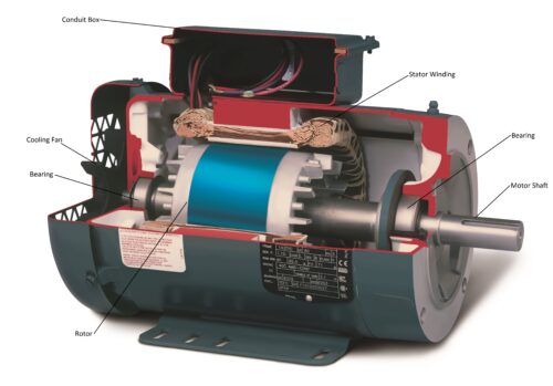
Figure
4: Cutaway view of an induction motor. Courtesy: ABB
If
the facility has a supervisory control and data acquisition system that allows
the networking of VFDs via Ethernet or fiber, the additional VFD parameters,
signals and statuses can be remotely monitored, such as real-time voltage,
current, power, output frequency, motor speed, motor torque and runtimes. This
kind of data is valuable for operators and maintenance to ensure the health and
longevity of their equipment.
Routine VFD and motor
maintenance considerations
All
equipment deteriorates over time, so it is crucial to test and maintain it
regularly to ensure it remains in good condition. Performing proper maintenance
is another key item that enhances the reliability of motors/VFD operations.
This includes preventive maintenance and visual inspections, cleaning filters
and vents from dust and debris. Motor and VFD inspections include checking for
proper ventilations, unusual noises and smells, corrosion and excessive
vibrations. Some preventive maintenance measures include applying lubrication,
tightening connections and replacing parts.
For
detailed maintenance and testing procedures, consider following the
manufacturer’s instructions and adhering to the recommended maintenance
guidelines from the InterNational
Electrical Testing Association and NFPA
70B: Standard for Electrical Equipment Maintenance.
Taha
Mohammed, PE, and Cole Casteel, PE, are electrical engineers with CDM Smith.
Do you have experience and
expertise with the topics mentioned in this content? You should consider
contributing to our WTWH Media editorial team and getting the recognition you
and your company deserve. Click here
to start this process.
Cole
Casteel, PE, and Taha Mohammed, PE
Author
Bio: Cole Casteel, PE, and Taha Mohammed, PE, are electrical engineers with CDM
Smith.
Source:
https://www.plantengineering.com/articles/how-to-ensure-reliable-motor-operation-with-variable-frequency-drives/